What should be considered when integrating an OEM TDLAS module? Integrating a TDLAS module requires managing four key engineering domains: pneumatics, power, thermal, and software. Key considerations include matching the gas flow rate (typically 1 L/min) without creating dead volumes, providing stable power capable of handling the initial TEC (Thermo-Electric Cooler) current spike, ensuring a clear thermal path to dissipate heat from the laser diode, and mapping the module's RS485/RS232/4-20mA output and status codes to the host instrument's controller.
1. The integration gap
Selecting a high-performance TDLAS module is only the first step in building a reliable gas analyser. The performance of the final instrument depends entirely on how well the module is integrated into the host system.
Too often, instrument makers treat gas modules as simple "black boxes" — provide power, pipe in gas, and read the output. This approach inevitably leads to problems during the prototype testing phase: delayed response times, thermal drift, or communication errors. To prevent these issues, mechanical and hardware engineers must address specific integration requirements before finalising their CAD models.
This checklist outlines the critical questions you must answer when integrating a module like the Specvaltech Line A OEM module.
2. Gas path & pneumatics
The optical cell inside the TDLAS module must receive a representative sample of the target gas as quickly as possible, without pressure fluctuations or condensation.
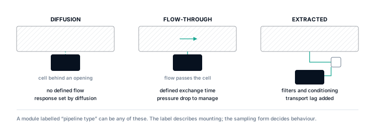
- Q1: Are the inlet and exhaust fittings compatible? Ensure your tubing matches the module's specified fittings (e.g., standard 6 mm or 1/4" pneumatic push-fit connectors).
- Q2: Is the flow rate matched? The Line A module is calibrated for a specific flow rate, typically 1 L/min. Your sampling pump must deliver this rate consistently. Too low, and the T90 response time will suffer. Too high, and you may introduce dynamic pressure errors.
- Q3: Have you minimised dead volume? Every centimetre of tubing between the sample inlet and the module adds to the system's response time. Keep the pneumatic path as short and direct as possible.
- Q4: How are you handling condensation? If the sample gas is hot and humid, it will condense when it hits the cooler tubing inside your instrument. You must design a sample conditioning system (water traps, coalescing filters, or heated lines) before the gas reaches the module.
3. Electrical & power
TDLAS modules contain delicate optoelectronics and microprocessors that require stable, clean power.
- Q5: Can your power supply handle the TEC spike? TDLAS lasers must be kept at a highly precise temperature. This is achieved using a Thermo-Electric Cooler (TEC). When the module is first powered on, or when the ambient temperature changes rapidly, the TEC draws a peak current that is significantly higher than the steady-state power consumption. Your DC 12 V supply must be rated to handle this transient spike without dropping voltage.
- Q6: Is the power supply clean? Switch-mode power supplies can introduce high-frequency ripple. Ensure your power conditioning circuit filters out noise that could interfere with the module's internal analog-to-digital converters.
- Q7: Are the grounds isolated? To prevent ground loops—especially in industrial environments—ensure the module's signal ground is properly isolated from the chassis ground if required by your system architecture.
4. Mechanical & thermal
The module must be securely mounted, but it also needs to breathe.
- Q8: Is the mounting stress-free? The module's optical bench is precisely aligned at the factory. Do not force the module into a warped chassis or over-tighten mounting screws, as mechanical stress can deform the optical cell and cause zero drift.
- Q9: Is there a clear thermal path? The heat generated by the module's electronics and the TEC must be dissipated. Do not pack the module tightly against other heat-generating components (like power supplies or large microprocessors) without adequate ventilation or a conductive path to a heat sink.
- Q10: Have you accounted for vibration? If the final instrument will be installed on vibrating machinery (like a pump station), use appropriate vibration-damping mounts to isolate the module.
5. Software & interface
Finally, your host controller must talk to the module effectively.
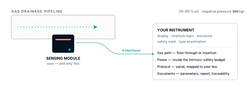
- Q11: Which physical layer are you using? The Line A module supports RS485, RS232, and 4–20 mA. Choose the interface that best matches your controller's capabilities and the required cable length. RS485 is recommended for high noise immunity.
- Q12: Are you parsing the status codes? The digital output provides more than just the concentration value. It includes status flags for laser temperature lock, low light intensity (dirty window warning), and internal faults. Your software must parse these codes and alert the user, rather than blindly displaying a concentration value when the module is reporting a fault.
6. Conclusion
Integrating an OEM TDLAS module is a multidisciplinary engineering task. By addressing these 12 questions during the initial design phase, you can avoid costly prototype revisions and ensure your final gas analyser delivers the performance and reliability your customers expect.
Ready to start your mechanical design?
We provide full 3D CAD models (STEP/IGES) and detailed interface documentation for the Line A module. Submit your project details to request the integration package.