What are the measurement nodes in a coal mine gas drainage network? A coal mine gas drainage network requires monitoring at four distinct nodes: Underground Mains (high negative pressure, extreme humidity), Branch Manifolds (dense multi-point measurement, space-constrained), Pump Station Headers (critical safety interlocks, highest reliability required), and Utilisation Feeds (positive pressure, high flow, custody-transfer accuracy). Each node presents unique physical conditions that dictate the choice between extractive OEM modules (Line A) and direct pipeline insertion modules (Line B).
1. The complexity of the drainage network
Coal mine gas drainage is not a single application; it is a vast, dynamic pneumatic network. The goal is to extract methane (CH₄) from the coal seam to ensure underground safety, and then transport that gas to the surface for power generation or flaring.
For system integrators and instrument manufacturers, providing a monitoring solution means designing equipment that can survive and measure accurately at various points along this network. Each point—or "node"—has a drastically different physical environment. A sensor that works perfectly at the surface utilisation plant will fail immediately if installed in an underground branch manifold.
This guide maps the four primary measurement nodes and explains the engineering logic for selecting the appropriate TDLAS measurement module.
2. Node 1: Underground mains
The underground main pipelines are the large arteries that carry the combined gas flow from multiple mining districts toward the surface.
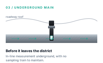
- The Environment: High negative pressure (often -40 to -80 kPa gauge), 100% relative humidity, liquid water flowing in the pipe, heavy coal dust, and strict intrinsic safety (Ex ia) requirements.
- The Challenge: Extractive sampling systems (pumps, filters, water traps) require constant maintenance, which is prohibitively expensive and difficult underground.
- The Solution: Direct pipeline insertion. The Line B module is designed for this exact node. It threads directly into a G1" fitting on the main pipe, eliminating the sampling train entirely. Its wide pressure compensation envelope ensures accurate readings despite the deep vacuum.
3. Node 2: Branch manifolds
Closer to the coal face, individual boreholes feed into smaller branch pipes, which are then grouped together at a manifold before joining the main.
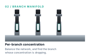
- The Environment: Similar to the mains (negative pressure, wet, dusty), but space is highly constrained. A single manifold station might require 10 to 20 separate measurement points.
- The Challenge: Installing 20 large, standalone insertion sensors on a single manifold is often physically impossible due to pipe spacing.
- The Solution: A hybrid approach. Integrators often build a central, intrinsically safe monitoring cabinet near the manifold. Here, a Line A OEM module can be used inside a multiplexed sampling system, where a single module sequentially measures gas drawn from the various branch pipes via pneumatic valves.
4. Node 3: Pump station headers
Located on the surface, the massive vacuum pumps are the heart of the network. The gas from the underground mains arrives here at the main suction header.
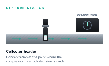
- The Environment: The highest negative pressure in the entire system. While it is on the surface (easier maintenance), the safety stakes are absolute. If the methane concentration drops into the explosive range (typically below 25-30 %vol depending on local regulations), the pumps must be shut down immediately to prevent an explosion.
- The Challenge: Speed and absolute reliability. The measurement cannot drift, and the response time must be instantaneous to trigger the safety interlock.
- The Solution: Redundant Line B insertion modules. By installing two or three Line B modules directly into the header pipe, the system achieves T90 < 5s response times with zero sampling delay. The WMS 2f/1f algorithm guarantees zero drift, ensuring the interlock threshold is never compromised by sensor degradation.
5. Node 4: Utilisation feeds
After passing through the pumps, the gas is pushed under positive pressure to gas engines (for electricity generation) or flares.
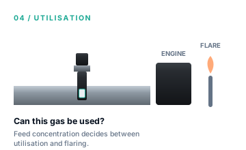
- The Environment: Positive pressure, high flow velocity. The gas is usually filtered and dried at this stage, making the environment much cleaner.
- The Challenge: Accuracy for energy calculation. The engine management system needs to know the exact methane concentration to adjust the air-fuel mix. If the gas is being sold to a third-party power plant, the measurement acts as a custody transfer point, requiring high precision.
- The Solution: The Line A module, integrated into a high-precision extractive analyser cabinet. Because the gas is clean and under positive pressure, sampling is easy. The Line A module provides the high-accuracy %vol measurement required for thermal energy calculations.
6. Conclusion
There is no "one size fits all" sensor for coal mine gas drainage. Successful instrument design requires matching the mechanical and algorithmic capabilities of the measurement module to the specific physics of the network node.
Which node are you designing for?
Tell us where your instrument will be installed in the drainage network. We will provide a technical assessment of the pressure, humidity, and safety requirements to recommend the correct module architecture.